9. Stress and equilibrium
After completing this chapter, you should be able to:
- Interpret internal forces as integrals of stresses over the cross-section
- Define the Cauchy stress tensor and derive the equilibrium of an infinitesimal volume element, \(\nabla\cdot\underline{\sigma} + \vec{f} = 0\)
- Apply the divergence theorem and the traction vector \(\vec{t} = \underline{\sigma}\cdot\hat{n}\)
- Formulate traction boundary conditions and interface conditions
From internal forces to stresses
In previous chapters, we analyzed beams using internal forces: the normal force \(N\), shear force \(Q\), and bending moment \(M\). These quantities are integrals over the cross-section of the beam and provide a simplified description of the mechanical state. However, they hide the detailed distribution of forces within the material. To understand how materials actually carry loads—and when they might fail—we need to look inside the beam and examine the stress distribution.
Consider slicing a beam perpendicular to its axis at some position \(x\). The slice has a cross-sectional area \(A\) with outward normal \(\hat{n}\) pointing in the positive \(x\)-direction. Before we made this imaginary cut, internal forces acted across this surface to hold the two parts of the beam together. These forces are distributed over the entire cross-section, not concentrated at a single point. We have so far ignored these distributed forces; all our beam were slender and we ignored the fact that they have finite thickness.
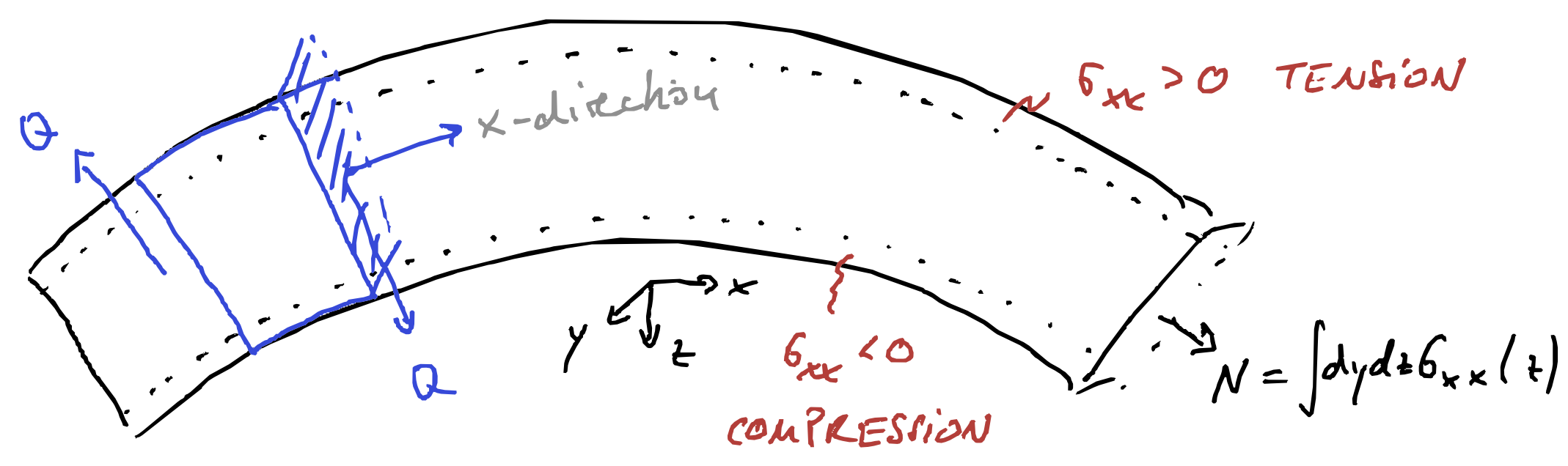
Figure 1 shows a beam with a negative bending moment. Examining a cross-sectional slice, we see that:
- The top of the beam is in tension (material is being pulled apart)
- The bottom is in compression (material is being pushed together)
- Somewhere in between lies the neutral axis whose length stays constant during bending
This distribution of tension and compression cannot be captured by a single force value. We need the concept of stress—force per unit area—to describe how the load is distributed across the section.
Internal forces as stress averages
The internal forces \(N\) and \(Q\) that we computed from equilibrium are actually averages (or more precisely, integrals) of specific stress tensor components over the cross-section:
Normal force is the integral of the normal stress \(\sigma_{xx}\) over the cross-section with area \(A\): \[N(x) = \int_A \mathrm{d}y\mathrm{d}z\,\sigma_{xx}(x,y,z) \tag{1}\]
Shear force is the integral of the shear stress \(\sigma_{xz}\) (or \(\tau_{xz}\)) over the cross-section: \[Q(x) = \int_A \mathrm{d}y\mathrm{d}z\,\sigma_{xz}(x,y,z) \tag{2}\]
Bending moment arises from the moment of the normal stress distribution about the neutral axis, which we assume to be located at \(z=0\): \[M(x) = \int_A \mathrm{d}y\mathrm{d}z\, z \sigma_{xx}(x,y,z) \tag{3}\]
These relationships reveal what internal forces truly represent: they are resultants of stress distributions. A constant normal stress \(\sigma_{xx} = N/A\) across the section would produce the same normal force \(N\), but as Figure 1 shows, the actual stress distribution in bending is far from constant.
The transition from internal forces to stresses is the transition from a 1D beam model to a 2D or 3D continuum description. While internal forces are sufficient for many engineering calculations, understanding stresses is essential for:
- Predicting where a structure will fail (stress concentrations)
- Designing structures with varying cross-sections
- Understanding strain near surfaces, for example to design sensors that measure deformation from surface strain
The stress tensor
In the beam analysis above, we encountered two stress components: the normal stress \(\sigma_{xx}\) (acting perpendicular to the cross-section) and the shear stress \(\sigma_{xz}\) (acting tangent to the cross-section). In a general three-dimensional solid, stresses can act on surfaces oriented in any direction, and the force on each surface can point in any direction. This requires a full tensor to describe.
Consider a small cubic element inside a solid (see e.g. Figure 2), with faces perpendicular to the \(x\), \(y\), and \(z\) axes. On each face, there can be a force per unit area (stress) that has components in all three directions. We use a double-index notation: \(\sigma_{ij}\) denotes the stress component where the first index \(i\) indicates the direction of the force and the second index \(j\) indicates the face on which the force acts (i.e., the face with normal in the \(j\)-direction).
The nine stress components can be organized into a 3×3 matrix called the stress tensor: \[\underline{\sigma} = \begin{pmatrix} \sigma_{xx} & \sigma_{xy} & \sigma_{xz} \\ \sigma_{yx} & \sigma_{yy} & \sigma_{yz} \\ \sigma_{zx} & \sigma_{zy} & \sigma_{zz} \end{pmatrix}\]
The diagonal components \(\sigma_{xx}\), \(\sigma_{yy}\), \(\sigma_{zz}\) are called normal stresses—they act perpendicular to the surface and cause tension (positive) or compression (negative). The off-diagonal components are called shear stresses—they act tangent to the surface and cause angular distortion. The shear stresses are often denoted with the symbol \(\tau\), so \(\tau_{xy} = \sigma_{xy}\), \(\tau_{xz} = \sigma_{xz}\), etc.
As we will show later in this chapter, moment equilibrium requires the stress tensor to be symmetric: \(\sigma_{ij} = \sigma_{ji}\). This means \(\tau_{xy} = \tau_{yx}\), \(\tau_{xz} = \tau_{zx}\), and \(\tau_{yz} = \tau_{zy}\), reducing the number of independent stress components from nine to six.
Static equilibrium
We will treat elasticity exclusively in the limit of small or infinitesimal strains where all equations are linear. The generalization of this “small strain” theory is “finite strain” elasticity which we will not treat in this class. We can make an analogy to the beam: Small strain means we will be ignoring rotations, as in Euler-Bernoulli beam theory. Note that linear elasticity is a classical field theory, this means all quantities typically depend continuously on positions \(\vec{r}\). Those quantities are called fields.
The central quantities of small strain elasticity are the (Cauchy) stress field \(\underline{\sigma }(\vec{r})\) and the displacement field \(\vec{u}(\vec{r})\). Given a material point has moved from position \(\vec{r}\) to \(\vec{r}^{\prime}\), the displacement field is \(\vec{u}(\vec{r})=\vec{r}^{\prime} -\vec{r}\). It therefore describes by how much a volume element in our deformed material has moved (or displaced) because of the deformation and is therefore the generalization of the fields \(u(x)\) and \(w(x)\) that we used to describe the deformation of beams.
The stress \(\underline{\sigma }\) is a tensor that transforms an area (vector) \(\vec{A}\) into a force vector \(\vec{F}\), \[\vec{F}=\underline{\sigma }\cdot \vec{A} \tag{4}\] Note that the area here is a vectorial quantity; the direction of this area vector points outwards on that area, i.e. \(\vec{A}=A \hat{n}\) where \(\hat{n}\) is the normal vector on the respective area.
In three-dimensions, the stress tensor is represented by a \(3\times 3\) matrix. A tensor describes a linear relationship between two quantities; the stress tensor describes the relationship between area of a virtual plane in our solid and the force acting on it, Equation 4. The fact that both force and normal vector of the area are represented in a certain coordinate system implies certain properties of the tensors, in particular for the transformation of the elements of the tensor under rotation of this coordinate system. We will discuss those in detail in Chapter 14. For the remainder of this chapter, we only need property Equation 4 of the stress tensor.
We will now consider the equilibrium of forces inside a solid body. Specifically, we regard a small volume element inside this body. Figure 2 a shows a sketch of some body with a volume element highlighted in red. If side lengths of the element \(\Delta x\), \(\Delta y\) and \(\Delta z\) are small enough, then the forces on opposite sites of the element must balance. We here denote the forces on the faces perpendicular to the \(x\)-direction by \(\vec{X}\), the forces on the \(y\)-faces by \(\vec{Y}\) and the forces on the \(z\)-faces by \(\vec{Z}\) (see Figure 2 b, \(z\)-direction not shown). If we know the areas, we can get the forces from the stress tensor \(\underline{\sigma }\) (that converts areas into forces, see Equation 4, specifically \[\vec{X} = \begin{pmatrix} \sigma_{xx} \Delta y \Delta z \\ \sigma_{yx} \Delta y \Delta z \\ \sigma_{zx} \Delta y \Delta z \end{pmatrix},\quad \vec{Y} = \begin{pmatrix} \sigma_{xy} \Delta x \Delta z \\ \sigma_{yy} \Delta x \Delta z \\ \sigma_{zy} \Delta x \Delta z \end{pmatrix} \quad\mathrm{and}\quad \vec{Z} = \begin{pmatrix} \sigma_{xz} \Delta x \Delta y \\ \sigma_{yz} \Delta x \Delta y \\ \sigma_{zz} \Delta x \Delta y \end{pmatrix}. \tag{5}\] Note that \(\vec{X}\), \(\vec{Y}\), \(\vec{Z}\) and \(\underline{\sigma }\) are fields; they explicitly depend on position \(\vec{r}\) within the body.
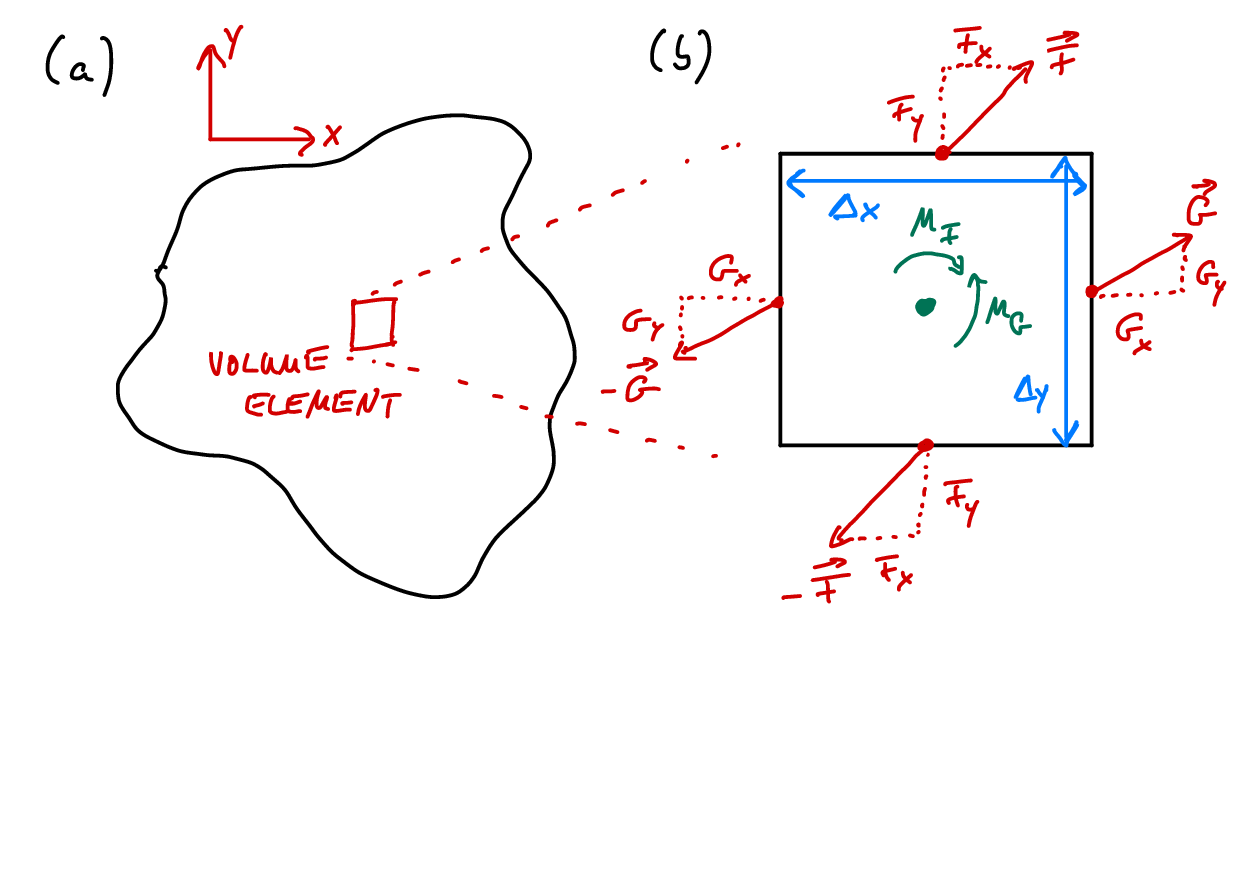
For a volume element located at position \(\vec{r}=(x,y,z)\), force equilibrium inside the element can be expressed as \[\begin{split}\vec{X}(x+\Delta x, y, z) - \vec{X}(x, y, z) &+ \vec{Y}(x, y+\Delta y, z) - \vec{Y}(x, y, z) \\ &+ \vec{Z}(x, y, z+\Delta z) - \vec{Z}(x, y, z) + \vec{F}(x,y,z) = 0 \end{split} \tag{6}\] where \(\vec{F}(x,y,z)\) is an external force, often called the body force, acting on the volume element. We can insert Equation 5 and divide by the volume of the element \(\Delta x \Delta y \Delta z\) to obtain \[\begin{equation} \begin{split} \frac{\sigma_{xx}(x+\Delta x,y,z)-\sigma_{xx}(x, y, z)}{\Delta x} &+ \frac{\sigma_{xy}(x,y+\Delta y,z)-\sigma_{xy}(x, y, z)}{\Delta y} \\ &+\frac{\sigma_{xz}(x,y,z+\Delta z)-\sigma_{xz}(x, y, z)}{\Delta z} + f_x(x,y,z) = 0 \end{split} \end{equation}\]for the \(x\)-component of Equation 6. Here \(f_x=F_x/\Delta x \Delta y \Delta z\) is a volume of body force. In the limit \(\Delta x\to 0\) and \(\Delta y\to 0\) this becomes \[\begin{equation} \frac{\partial \sigma_{xx}}{\partial x} + \frac{\partial \sigma_{xy}}{\partial y} + \frac{\partial \sigma_{xz}}{\partial z} + f_x = 0. \end{equation}\]From the \(y\) and \(z\)-component of Equation 6 we get two more differential equations,
\[\begin{align} \frac{\partial \sigma_{yx}}{\partial x} + \frac{\partial \sigma_{yy}}{\partial y} + \frac{\partial \sigma_{yz}}{\partial z} + f_y &= 0 \\ \frac{\partial \sigma_{zx}}{\partial x} + \frac{\partial \sigma_{zy}}{\partial y} + \frac{\partial \sigma_{zz}}{\partial z} + f_z &= 0. \end{align}\] These can be summarized to the compact notation \[\text{div}\, \underline{\sigma } + \vec{f} \equiv \nabla \cdot \underline{\sigma } + \vec{f} = 0, \tag{7}\] or in words: The divergence of the stress tensor balances the body force. Equation 7 is the central expression of elastostatics that describes force balance within a solid body.
Differential operators in tensor calculus are often defined by means of the Nabla operator \(\nabla\). In our typical \(3\)-dimensional Euclidean space it reads \[\nabla =\begin{pmatrix}\frac{\partial }{\partial x} \\ \frac{\partial }{\partial y} \\ \frac{\partial }{\partial z}\end{pmatrix}=\hat{x}\frac{\partial }{\partial x} + \hat{y}\frac{\partial }{\partial y} + \hat{z}\frac{\partial }{\partial z},\] where \(\hat{x}\) is the unit vector pointing in the \(x\)-direction. When applied to a second-rank tensor, our divergence operator “acts on the right”, i.e. \[\text{div}\, \underline{\sigma } = \nabla \cdot \underline{\sigma }=\sum_{j=1}^3 \frac{\partial\sigma_{ij}}{\partial r_j} \equiv \sigma_{ij,j},\] the derivative is taken with respect to the second index. Here, \(r_j\) is a component of the position vector \(\vec{r}\), i.e. \(r_1=x\), \(r_2=y\) and \(r_3=z\). This is a convention and you may encounter textbooks or publications that use different conventions.
An alternative derivation of force balance invokes the divergence theorem. The divergence theorem is an important result of vector analysis. It converts an integral over a volume \(V\) into an integral over the surface \(S\) of this volume. For a vector field \(\vec{f}(\vec{r})\), the divergence theorem states that \[\int_V \mathrm{d}^3 r\, \nabla \cdot \vec{f}(\vec{r}) = \int_{S} \mathrm{d}^2 r\, \vec{f}(\vec{r}) \cdot \hat{n}(\vec{r}) \tag{8}\] Here, \(\hat{n}(\vec{r})\) is the normal vector pointing outward on the surface \(S\) of the volume \(V\). We can integrate Equation 7 over a volume element inside this body of volume \(V\) and surface area \(S(V)\). Using the divergence theorem (sometimes also called Gauss’ theorem), we obtain \[\int_V \mathrm{d}^3 r\, \nabla \cdot \underline{\sigma } = \int_{S(V)} \mathrm{d}^2 r\,\underline{\sigma } \cdot \vec{e}_S = \int_{S(V)} \mathrm{d}^2 r\,\mathrm{d}\vec{F} = -\int_V \mathrm{d}^3 r\,\vec{f} \tag{9}\] where \(\vec{e}_S\) is the normal vector pointing outwards on \(S(V)\). The infinitesimal area vector \(\vec{e}_S \mathrm{d}^2 r\) is hence transformed into an (infinitesimal) force vector \(\mathrm{d}\vec{F} = \underline{\sigma } \cdot \vec{e}_S \mathrm{d}^2 r\) and integrated over. Equation 9 hence contains a sum over all forces acting on the surface of the volume element \(V\), and these forces must balance the body force. It is nothing else than a statement of force balance for any arbitrarily-chosen volume element \(V\) within the solid body.
Moment equilibrium
Besides equilibrium of forces, we also need to fulfill the equilibrium of moments acting on the volume element. The moment around the \(z\)-axis is given by \[\begin{equation} Y_x \Delta y + X_y \Delta x = 0 \end{equation}\]which immediately implies \(\sigma_{yx}=\sigma_{xy}\). The moment equilibrium around the \(x\)- and \(y\)-axes leads to conditions on the other off-diagonal components of \(\underline{\sigma }\), \(\sigma_{zx}=\sigma_{xz}\) and \(\sigma_{zy}=\sigma_{yz}\). By virtue of moment balance, the stress tensor is a symmetric tensor, \(\sigma_{ij}=\sigma_{ji}\) or \(\underline{\sigma }=\underline{\sigma }^T\).
Boundary conditions and surface tractions
The equilibrium equation \(\nabla \cdot \underline{\sigma} + \vec{f} = 0\) tells us how stresses must be distributed inside a solid body. But a differential equation alone does not uniquely determine the solution—we also need to specify what happens at the boundaries of the body. Think of it this way: knowing that water flows downhill (the governing equation) doesn’t tell you where the water will go unless you also know where the riverbanks are (the boundary conditions).
In elasticity, boundary conditions describe how a solid interacts with its environment at its surfaces. What forces are being applied? Is the surface free to move, or is it constrained? These boundary conditions are essential for solving any practical problem.
Surface traction
Every physical object has boundaries—the surfaces where the material ends and the surrounding environment begins. At these surfaces, external forces may act on the body. We need a way to describe these surface forces that is compatible with our stress tensor formulation.
The surface traction (or simply traction) is the force per unit area acting on a surface. If you imagine a small patch of surface area \(\Delta A\) experiencing a force \(\Delta \vec{F}\), the traction is: \[\vec{t} = \lim_{\Delta A \to 0} \frac{\Delta \vec{F}}{\Delta A}\] You have already encountered a form of traction in the previous chapters: The line load \(q(x)\), that describe the force per unit length on a beam. Dividing the line load by the width of the beam yields the normal traction on the surface.
The stress tensor provides a direct way to compute the traction on any surface. Given a surface with outward unit normal \(\hat{n}\) (we use hats to denote unit vectors, i.e., vectors of length one), the traction vector is \[\vec{t} = \underline{\sigma} \cdot \hat{n}, \tag{10}\] or in component notation \[t_i = \sum_{j=1}^3\sigma_{ij} n_j.\]
This is a fundamental relationship: once we know the stress tensor at a point, we can compute the force per unit area on any surface passing through that point—we just need to know the surface orientation \(\hat{n}\).
The traction vector generally has three components: one normal to the surface (the normal traction) and two tangential to the surface (the shear tractions). For example, consider a horizontal surface with its normal pointing in the \(z\)-direction (\(\hat{n} = \hat{z}\)). The traction components are: \[t_x = \sigma_{xz}, \quad t_y = \sigma_{yz}, \quad t_z = \sigma_{zz}\] Here \(t_z\) is the normal traction (it pushes or pulls perpendicular to the surface), while \(t_x\) and \(t_y\) are shear tractions (they act parallel to the surface).
Imagine pressing your hand flat against a table. The force your hand exerts on the table, divided by the contact area, is the traction. If you push straight down, you apply mostly normal traction. If you try to slide your hand while pressing down, you also apply shear traction. The traction vector captures both the magnitude and direction of this distributed surface force.
Traction boundary conditions
At the surface of a body, we can prescribe what traction must act there. This is called a traction boundary condition (also known as a Neumann boundary condition in the mathematical literature). Mathematically: \[\underline{\sigma} \cdot \hat{n} = \vec{t}_0 \quad \text{on surface } S \tag{11}\] where \(\vec{t}_0\) is the prescribed traction vector and \(\hat{n}\) is the outward normal to the surface.
Several important special cases arise frequently in practice:
Free surface (\(\vec{t}_0 = 0\)): No external force acts on the surface. This is the condition at any surface exposed to air (atmospheric pressure is usually negligible compared to stresses in solids). For a free surface with normal in the \(z\)-direction: \[\sigma_{xz} = 0, \quad \sigma_{yz} = 0, \quad \sigma_{zz} = 0 \quad \text{at the surface}\]
Pressure loading (\(\vec{t}_0 = -p\,\hat{n}\)): A uniform pressure \(p\) acts normal to the surface, pushing inward. The negative sign indicates that positive pressure creates compressive (inward) force. This occurs when a solid is submerged in a fluid or enclosed in a pressurized chamber. The line load of the previous chapters describes such pressure loading.
Applied force: When a concentrated force \(\vec{F}\) acts on a small area \(A\), the traction is approximately \(\vec{t}_0 = \vec{F}/A\). In reality, forces are always distributed over some area—point forces are idealizations that lead to stress singularities.
A traction boundary condition Equation 11 provides three equations (one for each component of \(\vec{t}_0\)). For a surface with normal \(\hat{n} = \hat{z}\), these equations directly specify \(\sigma_{xz}\), \(\sigma_{yz}\), and \(\sigma_{zz}\) at the surface. The other stress components (\(\sigma_{xx}\), \(\sigma_{yy}\), \(\sigma_{xy}\)) are not constrained by this boundary condition—they are determined by equilibrium in the interior and other boundary conditions elsewhere.
Continuity conditions at interfaces
When two different materials are bonded together, the interface between them requires special consideration. Two fundamental conditions must be satisfied:
Traction continuity: The traction must be the same on both sides of the interface: \[\underline{\sigma}^{(1)} \cdot \hat{n} = \underline{\sigma}^{(2)} \cdot \hat{n} \tag{12}\] where superscripts (1) and (2) denote the two materials and \(\hat{n}\) is the interface normal. This is simply Newton’s third law: if material 1 pushes on material 2 with some force per unit area, then material 2 must push back on material 1 with an equal and opposite force per unit area.
Displacement continuity (for bonded interfaces): If the materials are bonded (glued, welded, etc.), they must move together: \[\vec{u}^{(1)} = \vec{u}^{(2)}\] If this condition is violated, the materials would separate or interpenetrate—which is physically impossible for a bonded interface.
Consider cutting an elastic body along any internal surface. The internal forces that were acting across this surface must be equal and opposite on the two newly created surfaces. This is simply Newton’s third law applied to the internal stress distribution. The traction \(\vec{t} = \underline{\sigma} \cdot \hat{n}\) represents this internal force per unit area.
This chapter introduced stress and the equilibrium of a continuum:
- Internal forces as stress averages: \(N = \int_A \sigma_{xx}\,\mathrm{d}A\), \(Q = \int_A \sigma_{xz}\,\mathrm{d}A\)
- Stress tensor: \(\sigma_{ij}\) is the \(j\)-component of the force per unit area on a surface with normal \(i\); it is symmetric
- Equilibrium of a volume element: \(\partial_j\sigma_{ij} + f_i = 0\), i.e. \(\nabla\cdot\underline{\sigma} + \vec{f} = 0\)
- Surface traction: \(\vec{t} = \underline{\sigma}\cdot\hat{n}\); traction boundary conditions prescribe \(\vec{t}\) on the surface, free surfaces have \(\vec{t} = 0\)
- Interfaces: traction is continuous (Newton’s third law)
This is the third time we write a mechanical balance from the equilibrium of forces: for a rigid body, for an infinitesimal beam element and now for an infinitesimal volume element.