5. Beam kinematics

TipLearning Objectives

After completing this chapter, you should be able to:

  • Define the kinematic quantities of a beam: axial displacement \(u\), deflection \(w\), rotation \(\varphi\)
  • Derive the strain measures \(\varepsilon = u'\), \(\gamma = w' + \varphi\) and \(\chi = \varphi'\) from the deformation of an infinitesimal beam element
  • Distinguish rigid rotation of the cross-section from shear deformation

We now transition from the study of rigid bodies and internal forces to the kinematics of deformable bodies. In this chapter, we focus on beams, which are one-dimensional structural elements where one dimension (the length along the beam axis) is significantly larger than the other two dimensions (width and height of the cross-section).

The kinematics of beams describes how points in the beam move and deform when subjected to loads. Unlike rigid bodies where deformation is ignored, beam kinematics explicitly accounts for changes in shape and curvature.

Beam geometry and coordinates

Consider a straight beam of length \(L\) oriented along the \(x\)-axis. The beam has a cross-section in the \(y\)-\(z\) plane, where \(z\) is the direction perpendicular to the beam axis in which bending occurs. We focus on deformation in the \(x\)-\(z\) plane.

Code
import numpy as np
import matplotlib.pyplot as plt
from matplotlib.patches import Rectangle, FancyArrowPatch

fig, ax = plt.subplots(figsize=(7, 3))

# Colors
beam_color = '#cccccc'

# Beam dimensions
L = 1.0
beam_height = 0.1

# Draw the beam
beam = Rectangle((0, -beam_height/2), L, beam_height,
                  facecolor=beam_color, edgecolor='black', linewidth=2)
ax.add_patch(beam)

# Draw coordinate axes
ax.annotate('', xy=(1.2, 0), xytext=(0, 0),
            arrowprops=dict(arrowstyle='->', color='black', lw=2))
ax.text(1.25, 0, r'$x$', fontsize=14, va='center')

ax.annotate('', xy=(0, -0.25), xytext=(0, 0),
            arrowprops=dict(arrowstyle='->', color='black', lw=2))
ax.text(0.03, -0.28, r'$z$', fontsize=14, ha='left')

# Mark beam axis
ax.plot([0, L], [0, 0], 'k--', linewidth=1, alpha=0.5)
ax.text(0.5, 0.02, 'beam axis', fontsize=10, ha='center', va='bottom', style='italic')

ax.set_xlim(-0.1, 1.4)
ax.set_ylim(-0.35, 0.2)
ax.set_aspect('equal')
ax.axis('off')

plt.tight_layout()
plt.show()
Figure 1: Beam geometry showing the coordinate system. The beam extends along the \(x\)-axis with the \(z\)-axis pointing downward.

Figure 1 shows an undeformed beam. The beam axis passes through the centroid of the cross-section. In the undeformed configuration, this axis is a straight line along the \(x\)-direction. We will in the following assume that the beam is a slender object, i.e. we can ignore its finite thickness.

Kinematic quantities

When a beam deforms, we describe its motion using two fundamental displacement quantities measured at the beam axis. The axial displacement \(u(x)\) describes the displacement of the beam axis in the \(x\)-direction. The deflection \(w(x)\) is the displacement of the beam axis in the \(z\)-direction (perpendicular to the beam). In addition to translation, cross-sections of the beam can rotate. We denote the rotation of a cross-section by \(\varphi(x)\), measured positive counterclockwise (i.e., a positive rotation tilts the cross-section such that its top moves in the negative \(x\)-direction). Figure 2 illustrates these quantities.

Code
import numpy as np
import matplotlib.pyplot as plt
from matplotlib.patches import Rectangle, FancyArrowPatch, Arc
import matplotlib.transforms as transforms

fig, ax = plt.subplots(figsize=(7, 3))

# Colors
beam_color = '#cccccc'
deformed_color = '#e0e0e0'
arrow_color = '#008fe0'

# Beam dimensions
L = 1.0
beam_height = 0.08

# Draw undeformed beam (dashed outline)
ax.plot([0, L], [-beam_height/2, -beam_height/2], 'k--', linewidth=1, alpha=0.5)
ax.plot([0, L], [beam_height/2, beam_height/2], 'k--', linewidth=1, alpha=0.5)
ax.plot([0, 0], [-beam_height/2, beam_height/2], 'k--', linewidth=1, alpha=0.5)
ax.plot([L, L], [-beam_height/2, beam_height/2], 'k--', linewidth=1, alpha=0.5)
ax.text(0.5, beam_height/2 + 0.03, 'undeformed', fontsize=9, ha='center', style='italic', alpha=0.7)

# Draw deformed beam (shifted and deflected downward with z pointing down)
u_val = 0.08  # axial displacement
w_val = 0.12  # deflection (positive = downward in z-down convention)

# Deformed beam - simple representation with curved axis
x_def = np.linspace(0, L, 50)
# Cubic deflection shape (negative in plot since z points down but plot y points up)
w_def = -w_val * (3*(x_def/L)**2 - 2*(x_def/L)**3)
u_def = u_val * x_def/L

# Draw deformed beam outline (approximate)
ax.fill_between(x_def + u_def, w_def - beam_height/2, w_def + beam_height/2,
                facecolor=deformed_color, edgecolor='black', linewidth=1.5, alpha=0.8)

# Draw beam axis (deformed)
ax.plot(x_def + u_def, w_def, 'k-', linewidth=1)

# Mark a specific cross-section location
x_cs = 0.7
idx = int(x_cs/L * 49)
x_cs_def = x_cs + u_def[idx]
w_cs_def = w_def[idx]

# Calculate local rotation at this point (slope in plot coordinates)
dw_dx_plot = -w_val * (6*x_cs/L - 6*(x_cs/L)**2) / L
phi_local = np.arctan(dw_dx_plot)

# Draw the rotated cross-section
cs_length = 0.12
dx = -cs_length/2 * np.sin(phi_local)
dz = cs_length/2 * np.cos(phi_local)
ax.plot([x_cs_def - dx, x_cs_def + dx], [w_cs_def - dz, w_cs_def + dz],
        'b-', linewidth=3)

# Draw original cross-section position (vertical line)
ax.plot([x_cs, x_cs], [-cs_length/2, cs_length/2], 'b--', linewidth=2, alpha=0.5)

# Arrow for u (axial displacement)
ax.annotate('', xy=(x_cs_def, 0.08), xytext=(x_cs, 0.08),
            arrowprops=dict(arrowstyle='->', color=arrow_color, lw=2))
ax.text((x_cs + x_cs_def)/2, 0.11, r'$u$', fontsize=14, ha='center', color=arrow_color)

# Arrow for w (deflection - pointing down since z is down)
ax.annotate('', xy=(x_cs + 0.12, w_cs_def), xytext=(x_cs + 0.12, 0),
            arrowprops=dict(arrowstyle='->', color=arrow_color, lw=2))
ax.text(x_cs + 0.15, w_cs_def/2, r'$w$', fontsize=14, ha='left', color=arrow_color)

# Arc for rotation phi (clockwise rotation for downward deflection)
arc_radius = 0.08
arc = Arc((x_cs_def, w_cs_def), 2*arc_radius, 2*arc_radius,
          angle=0, theta1=90 + np.degrees(phi_local), theta2=90,
          color=arrow_color, linewidth=2)
ax.add_patch(arc)
ax.text(x_cs_def - 0.02, w_cs_def - arc_radius - 0.02, r'$\varphi$',
        fontsize=14, ha='center', va='top', color=arrow_color)

# Coordinate axes
ax.annotate('', xy=(1.25, 0), xytext=(-0.05, 0),
            arrowprops=dict(arrowstyle='->', color='black', lw=1.5))
ax.text(1.28, 0, r'$x$', fontsize=12, va='center')

ax.annotate('', xy=(-0.05, -0.22), xytext=(-0.05, 0),
            arrowprops=dict(arrowstyle='->', color='black', lw=1.5))
ax.text(-0.03, -0.25, r'$z$', fontsize=12, ha='left')

ax.set_xlim(-0.15, 1.4)
ax.set_ylim(-0.3, 0.18)
ax.set_aspect('equal')
ax.axis('off')

plt.tight_layout()
plt.show()
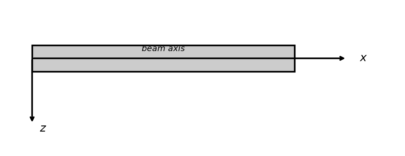
Figure 2: Kinematic quantities for beam deformation: axial displacement \(u\), deflection \(w\), and rotation \(\varphi\) of a cross-section.

Strain measures

The kinematic quantities \(u\), \(w\), and \(\varphi\) describe the motion of the beam. Any physical properties, such as the internal forces described in the previous chapter, cannot depend on these kinematic quantities. Image we are just stretching the beam, then intuitively the normal force should be constant across the beam. However, the displacement at the left will be zero while the displacement at the very right end of the beam will be finite.

Axial strain

Any physical property can only depend on the relative motion of material inside the beam. The measures that describe this local deformation are called strains. The axial strain \(\varepsilon\) measures the stretching or compression of the beam axis. To motivate the final expression, let us pick a point \(x_0\) somewhere inside the beam. The normal displacement is \(u(x_0)\). A point a distance \(\mathrm{d}x\) to the right of \(x_0\) is \(u(x_0+\mathrm{d}x)\). The relative displacement is hence \(u(x_0+\mathrm{d}x)-u(x_0)\). The strain is this expansion normalized by the distance \(\mathrm{d}x\) across which we are monitoring the displacement. Relative expansion of the beam section is \[\varepsilon = \frac{u(x_0+\mathrm{d}x)-u(x_0)}{\mathrm{d}x} = \frac{\mathrm{d}u}{\mathrm{d}x}.\] A positive axial strain \(\varepsilon\) corresponds to elongation of the beam.

Shear strain

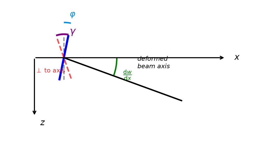
The slope of the deformed beam axis is \(\mathrm{d}w/\mathrm{d}x\). This slope can be decomposed into two contributions: A rotation \(\varphi\), which is the rigid body rotation of the cross-section (positive counterclockwise), and a shear strain \(\gamma\), the angular distortion due to shear deformation.

With \(z\) pointing downward and \(\varphi\) positive counterclockwise, a positive slope \(\mathrm{d}w/\mathrm{d}x\) (beam deflecting further down as \(x\) increases) corresponds to a clockwise rotation, which is negative \(\varphi\). Therefore: \[\frac{\mathrm{d}w}{\mathrm{d}x} = \gamma-\varphi\]

Rearranging, the shear strain \(\gamma\) measures the angular deviation between the cross-section orientation and the beam axis slope: \[\gamma = \frac{\mathrm{d}w}{\mathrm{d}x} + \varphi\]

Code
import numpy as np
import matplotlib.pyplot as plt
from matplotlib.patches import Arc, FancyArrowPatch

fig, ax = plt.subplots(figsize=(7, 3))

# Colors
beam_color = '#cccccc'
arrow_color = '#008fe0'

# Draw a beam element
element_length = 0.4
element_height = 0.15

# Undeformed element (reference)
ax.plot([0, element_length], [0, 0], 'k--', linewidth=1, alpha=0.5)
ax.plot([0, 0], [-element_height/2, element_height/2], 'k--', linewidth=1.5, alpha=0.5)

# Deformed configuration (z points down, so positive dw/dx means beam axis goes down)
dw_dx = 0.35  # slope of beam axis (positive = going down in z-down convention)
phi = 0.20    # rotation of cross-section (positive = clockwise in z-down convention)
gamma = dw_dx - phi  # shear strain

# Draw deformed beam axis (going downward in plot = positive slope in z-down)
ax.plot([0, element_length], [0, -element_length * np.tan(dw_dx)], 'k-', linewidth=2)
ax.text(element_length/2 + 0.05, -element_length/2 * np.tan(dw_dx) + 0.03,
        'deformed\nbeam axis', fontsize=9, ha='left', va='bottom', style='italic')

# Draw rotated cross-section (clockwise rotation = positive phi in z-down)
cs_length = element_height
x_cs = 0
z_cs = 0
dx = cs_length/2 * np.sin(phi)  # clockwise rotation
dz = cs_length/2 * np.cos(phi)
ax.plot([x_cs - dx, x_cs + dx], [z_cs - dz, z_cs + dz], 'b-', linewidth=3)

# Draw line perpendicular to beam axis (for reference)
perp_angle = np.pi/2 + np.arctan(dw_dx)
dx_perp = cs_length/2 * np.cos(perp_angle)
dz_perp = cs_length/2 * np.sin(perp_angle)
ax.plot([x_cs - dx_perp, x_cs + dx_perp], [z_cs - dz_perp, z_cs + dz_perp],
        'r--', linewidth=2, alpha=0.7)
ax.text(-dx_perp - 0.02, -dz_perp + 0.02, r'$\perp$ to axis', fontsize=9,
        ha='right', color='red', alpha=0.8)

# Arc for dw/dx (slope angle, measured from horizontal going down)
arc_radius = 0.18
arc1 = Arc((0, 0), 2*arc_radius, 2*arc_radius,
           angle=0, theta1=-np.degrees(np.arctan(dw_dx)), theta2=0,
           color='green', linewidth=2)
ax.add_patch(arc1)
ax.text(arc_radius + 0.02, -0.04, r'$\frac{\mathrm{d}w}{\mathrm{d}x}$',
        fontsize=12, ha='left', va='top', color='green')

# Arc for phi (rotation of cross-section from vertical, clockwise)
arc_radius2 = 0.12
arc2 = Arc((0, 0), 2*arc_radius2, 2*arc_radius2,
           angle=0, theta1=90 - np.degrees(phi), theta2=90,
           color=arrow_color, linewidth=2)
ax.add_patch(arc2)
ax.text(0.02, arc_radius2 + 0.02, r'$\varphi$', fontsize=12, ha='left', color=arrow_color)

# Arc for gamma (shear strain = angle between cross-section and perpendicular to axis)
arc_radius3 = 0.08
theta_perp = 90 + np.degrees(np.arctan(dw_dx))
theta_cs = 90 - np.degrees(phi)
arc3 = Arc((0, 0), 2*arc_radius3, 2*arc_radius3,
           angle=0, theta1=theta_cs, theta2=theta_perp,
           color='purple', linewidth=2.5)
ax.add_patch(arc3)
ax.text(0.02, 0.08, r'$\gamma$', fontsize=14, ha='left', color='purple', fontweight='bold')

# Coordinate axes
ax.annotate('', xy=(0.55, 0), xytext=(-0.1, 0),
            arrowprops=dict(arrowstyle='->', color='black', lw=1.5))
ax.text(0.58, 0, r'$x$', fontsize=12, va='center')

ax.annotate('', xy=(-0.1, -0.2), xytext=(-0.1, 0),
            arrowprops=dict(arrowstyle='->', color='black', lw=1.5))
ax.text(-0.08, -0.23, r'$z$', fontsize=12, ha='left')

ax.set_xlim(-0.2, 0.65)
ax.set_ylim(-0.28, 0.18)
ax.set_aspect('equal')
ax.axis('off')

plt.tight_layout()
plt.show()
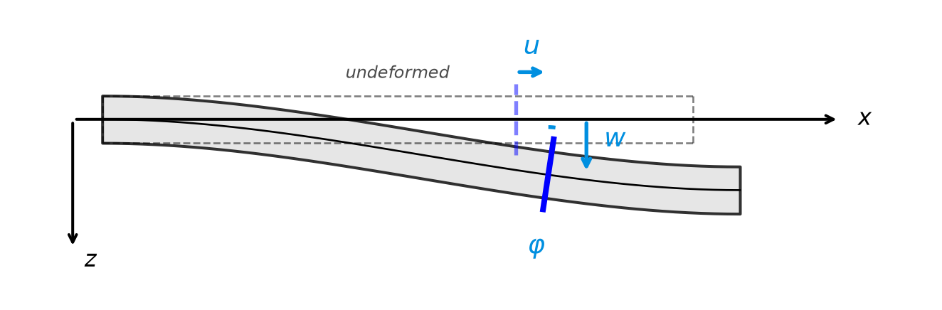
Figure 3: Shear strain \(\gamma\) as the sum of the slope of the beam axis \(\mathrm{d}w/\mathrm{d}x\) and the rotation of the cross-section \(\varphi\).

If the cross-section remains perpendicular to the deformed beam axis (as in Bernoulli beam theory), then \(\varphi = -\mathrm{d}w/\mathrm{d}x\) and \(\gamma = 0\). A non-zero shear strain indicates that the cross-section is not perpendicular to the beam axis.

Curvature

The curvature \(\chi\) measures the rate of change of rotation along the beam: \[\chi = \frac{\mathrm{d}\varphi}{\mathrm{d}x}\]

Curvature quantifies how much the beam bends per unit length. A positive curvature corresponds to the beam curving such that the center of curvature is below the beam (concave downward in the z-down convention).

NoteSummary of kinematic relations

The kinematic quantities and their relationships are:

Quantity Symbol Definition Physical meaning
Axial displacement \(u\) — Motion along beam axis
Deflection \(w\) — Motion perpendicular to beam
Rotation \(\varphi\) — Rotation of cross-section
Axial strain \(\varepsilon\) \(\mathrm{d}u/\mathrm{d}x\) Stretching of beam axis
Shear strain \(\gamma\) \(\mathrm{d}w/\mathrm{d}x + \varphi\) Angular distortion
Curvature \(\chi\) \(\mathrm{d}\varphi/\mathrm{d}x\) Bending per unit length
NoteChapter Summary

This chapter introduced the kinematics of deformable beams:

  • Kinematic quantities: axial displacement \(u\), deflection \(w\), rotation \(\varphi\) of the cross-section
  • Axial strain: \(\varepsilon = \mathrm{d}u/\mathrm{d}x\) (stretching of the beam axis)
  • Shear strain: \(\gamma = \mathrm{d}w/\mathrm{d}x + \varphi\) (angle between cross-section and normal to the axis)
  • Curvature: \(\chi = \mathrm{d}\varphi/\mathrm{d}x\) (bending per unit length)

Each strain measure will turn out to be conjugate to one internal force: \(N\) to \(\varepsilon\), \(Q\) to \(\gamma\), \(M\) to \(\chi\). The next chapter makes this precise with the principle of virtual work.